Geometry Of the Base Element
Classical Design
The classical EMVS array consists of three short dipoles and three small loops,
as in Fig.1, each connected to its own receiver
[201]:
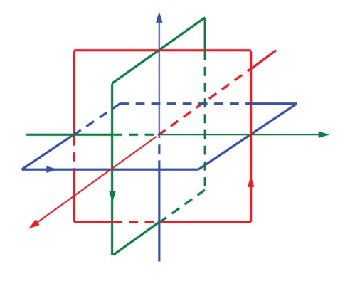
Fig.1. Classical EMVS
Modified Design
As demonstrated in [202],
the dipoles could be eliminated if the
loops are loaded with two receivers at the opposite sides, then each element serves
both as a loop and as a dipole. Two such elements are shown on Fig.2:

Fig.2. Double loaded loops
Proposed Design
We propose a slightly modified version of the double-loaded loop element
as shown on Fig. 3, where the receivers are located at the loop center and
connected to the opposite corners of the loop with open wire feedlines:

Fig.3. Proposed base element
The signals from the two receivers are fed to the PC, and their
sum and difference are computed. When the two signals are added in-phase (Sig = RX1 + RX2),
the element works as a vertical dipole, with the upper and lower triangles
serving as dipole shoulders; when the signals are added 180 degrees out of phase
(Sig = RX1 - RX2),
the element turns into a K6STI receiving loop
[203], also known as Alford loop
[204] and LZ1AQ crossed parallel loop
[205]. If only one of the signals
is used and the other one is discarded (Sig = RX1), this element becomes a
W2PM Mini Diamond Flag
[206].
Validation
To validate the proposed element design, 4nec2 antenna modeling software
[207]
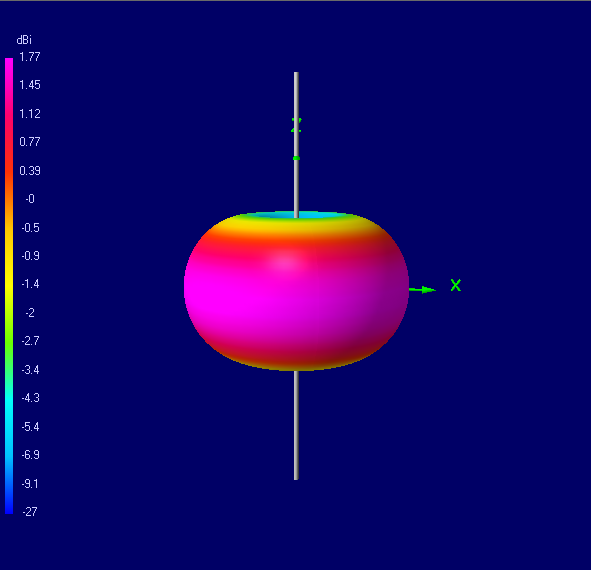
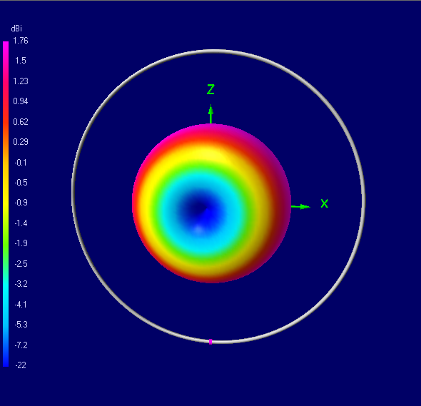
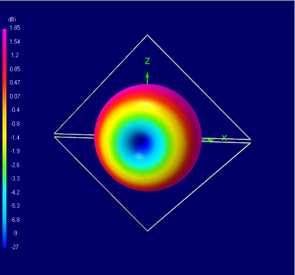
was used to compute the 3D radiation patterns of a short dipole, small
loop, and the proposed double-loaded element in the dipole, loop and flag modes.
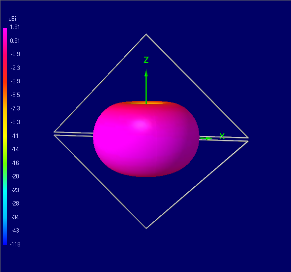
The computed patterns are shown on Fig.4 and Fig.5.
a
b
Fig.4. 3D radiation patterns of a short dipole (a) and a small loop (b)
a
b
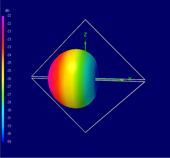
c
Fig.5. 3D radiation patterns of a double-loaded element in the
dipole (a), loop (b) and diamond flag (c) modes
As expected, all patterns are toroids, except that of the diamond flag, which is
a 3D cardioid. The radiation patterns of the double-loaded element in the dipole
and loop modes are identical to those of the short dipole and small loop antennas
respectively.
Proposed EMVS Array
Three mutually orthogonal double-loaded loops form the proposed EMVS receiving
antenna array.
The elements of the array may be oriented either as shown on Fig.6,
or in the ground-symmetric way
as suggested in [208]. In the latter case,
the antenna is rotated so that one of the triangles that form its octahedron
shape is parallel to the ground.
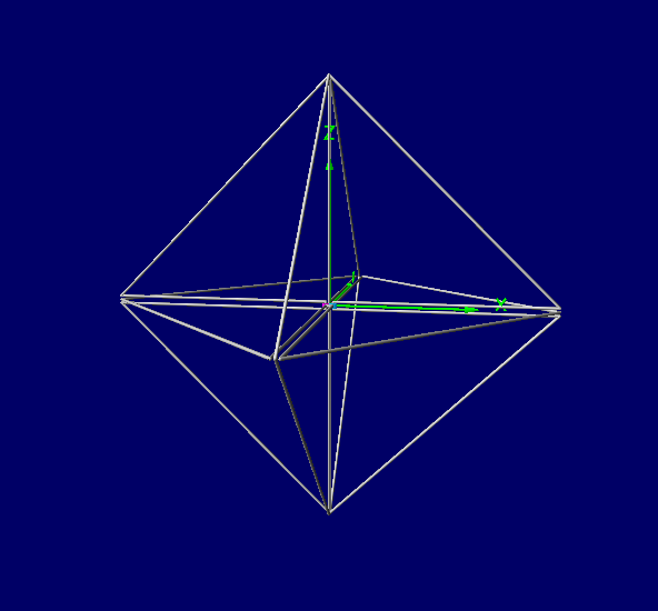
Fig.6. Proposed EMVS Array