Overview
Concept
Electromagnetic Vector Sensor (EMVS), first described by Dr. Nehorai
[1],[2]
in 1991, is currently a subject of active scientific research. It is used
in mobile communications for direction finding, beam forming, and polarization
matching.
In its classical form, EMVS consists of three mutually orthogonal dipoles,
and three mutually orthogonal loops. All six antennas are collocated
(their geometric centers coincide). An array of six synchoronized SDR receivers
serves as an interface between the sensor and a computer. Using this setup,
it is possible to measure the X,Y,Z components of the E and H vectors of the
impinging radio wave.
Full information about the E and H vectors allows the PC software
to do many interesting things
[3],[4],
such as:
-
determine the direction of arrival of the radio waves, both in the azimuth
and elevation planes, with high accuracy. This may be done simply by computing
the cross product of the E and H vectors;
-
determine the complete polarization state of the radio wave, linear, circular or
elliptic, and adaptively match the polarization of the receiving system;
-
separate multiple signals on the same frequency if they come from different
directions, or at different vertical angles, or if they at least have different
polarization.
Advantages
EMVS exploits the pattern and polarization diversity of its receiving elements,
and this gives it several advantages over the phased arrays of identical elements
that exploit spatial diversity:
- it can receive signals from any direction and with any polarization;
- collocation of its elements results in a compact design that does not
require a lot of real estate;
- the EMVS system can be made wideband because it does not
depend on the distances between the elements being a certain fraction of the
wavelength.

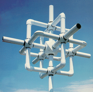
Fig.1. A commercial EMVS antenna
Possible Applications in Ham Radio
- EMVS used as a receiving antenna will eliminate most of the QSB by tracking
the Faraday rotation of the polarization vector and adaptively changing the
polarization of the antenna.
- Automatic separation of multiple signals on the same frequency
will counteract deliberate QRM in the pileups.
- The ability to measure the azimuth and elevation of the radio wave arrival
with high accuracy will be extremely valuable for propagation research;
- High resolution azimuth estimation will make detection of the pirate
stations much easier;
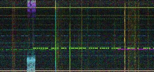
- Azimuth information will provide another clue for finding DX signals on the
crowded bands. Just imagine a color-coded waterfall display on the HF bands,
similar to what DF6NM has done on VLF, where the color indicates the direction
of arrival:

Fig.2. Color-coded waterfall display on VLF


