Parameters Of the Base Element
The double-loaded loop element described in the
previous section
has several parameters that need to be selected.
Load Impedance
The input impedance of the receivers connected to the loop element affects
sensitivity, frequency response and receiving pattern of the antenna.
I have created a NEC-2
 model
of the double-loaded element to study its characteristics as af function of load
impedance. The size of the element in this model was 1 m per side, and the
element was made of #14 wire. The results of the modeling are shown on Fig.1.
The value plotted on the chart is signal power, in dBm, that the antenna
delivers to the input of the receiver when the external field strength is 1 V/m.
The chart data are available in a
grf file which you can open
using the Graph software
[300].
model
of the double-loaded element to study its characteristics as af function of load
impedance. The size of the element in this model was 1 m per side, and the
element was made of #14 wire. The results of the modeling are shown on Fig.1.
The value plotted on the chart is signal power, in dBm, that the antenna
delivers to the input of the receiver when the external field strength is 1 V/m.
The chart data are available in a
grf file which you can open
using the Graph software
[300].
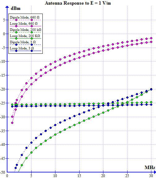
Fig.1. Sensitivity of the double-loaded loop
Several publications
[301]
[204]
state that a small wideband loop must be loaded with a low-impedance amplifier,
so the first value I tried was 3Ω as suggested in
[204].
The chart demonstrates that the frequency response of the element in the
loop mode (Sig = RX1 - RX2) loaded with 3Ω (solid blue line) is extremely flat,
which is probably the reason why low impedance loading is recommended for
small receiving loops. Unfortunately, the sensitivity of the loop with such
loading is very low. In the dipole mode (Sig = RX1 + RX2), the frequency responce
is not flat at all but still very low (the dotted blue line).
For a short dipole receiving antenna, a high input impedance amplifier is recommended
[302].
The plot for high impedance (200 kΩ) loading (the green
lines on the chart) is flat in the dipole mode and varies widely in the loop mode.
The sensitivity is as poor as with low impedance loading.
The sensitivity peaks at a load impedance around 650Ω.
Also, at this loading the element has about the same gain in the dipole
and loop modes (the pink lines on the chart).
This is almost the same load impedance as used in the W2PM Mini Diamond Flag
[206].
We choose the input impedance of 650Ω for the receivers because this
results in the the best sensitivity
and good balance between the loop and dipole modes.
Feedline Parameters
The short runs of open-wire feedline that connect the receivers to the loop element
must have the same characteristic impedance as the input impedance of the receivers.
We choose the distance of 5 cm between the wires of the feedline.
This results in the characteristic impedance of 500Ω, which is close
enough to the ideal value of 560Ω and results in a compact size of the structure.
Loop Size
The size of the loop is a compromise between the conflicting requirements
of high sensitivity and small dimensions. I have created the NEC-2
models of
several popular receiving antennas to see how the proposed element compares
to other solutions. The sensitivity charts are shown on Fig.2., they include
only some of the modeled antennas to avoid cluttering. All charts are available
in the
grf file.
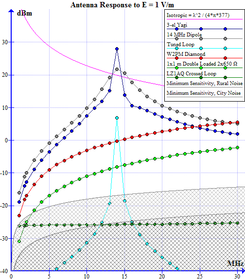
Fig.2. Sensitivity of some HF antennas
Some familiar relationships appear on this chart. The sensitivity of a dipole
at its resonant frequency is 2 dB better than that of an isotropic antenna
(2 dBi gain), and a 3-element Yagi has a gain of 8 dBi. A tuned 1x1 m loop
is better than the wideband W2PM Diamond Flag, and a 1x1 m wideband crossed loop
with low impedance loading is the least sensitive of all modeled antennas.
The 1x1 m double loaded element is in the middle of the chart. Its sensitivity
is not as good as that of the full size or tuned antennas, but it is more sensitive
than a loop of the same size loaded with 3Ω, by up to 20 dB at high frequencies.
The shadowed areas represent the minimum sensitivity that is required
to make the power of the external noise picked up by the antenna equal to the
power of the internal noise of the receiver, assuming the receiver's noise
figure of 10 dB. The external noise was modeled as man-made noise specified in
the ITU Recommendation
[303]. Other noise types, such as
atmospheric and galactic noise, when taken into account, may relax the requirements
to the receiver sensitivity. It follows from the chart that the proposed
receiving element has sufficient sensitivity on the frequencies above 3 MHz.
The sensitivity may be increased by increasing the size of the loop. With a size
of 1.5 m per side, the element has the same sensitivity as W2PM Diamond Flag.
We choose the size of 1x1 m for the double loaded element
because this results in the adequate antenna sensitivity. The size may be
increased to 1.5x1.5 m if more sensitivity is required.